User:Brendlefly62/Rockchip RK3399 Asus Tinker Board 2 S
Construction of this page began 8 May 2024 (work in progress)
This is a relatively inexpensive ($119 on Amazon as of 5/8/2024 Amazon link) armv8 SBC based on the Rockchip rk3399 SoC, made by a very popular motherboard manufacturer (Asus). See details below. This system runs Gentoo Linux, with further objectives, as described below.


Overall status
This will eventually be a complete built-from-scratch system. Currently, the board has a Gentoo rootfs system, a custom amd64-cross-compiled kernel built using kernel.org upstream sources. The board is currently using the bootloader installed on the boot device with a custom-built Armbian image. The author's intent is to create a custom amd64-cross-compiled u-boot bootloader to replace the last remaining component "built by others."
Hardware
| Make/model | Notes | |
|---|---|---|
Board |
Asus Tinkerboard 2 S | Manual
dtb: rk3399-tinker-2-s.dtb |
SoC |
Rockchip RK3399-T | quickstart guide |
RAM |
2GB | Dual-CH LPDDR4 2GB |
Firmware |
** Currently as provided by custom-built Armbian Image | To do: Custom-cross compile u-boot by on gentoo amd64 desktop PC |
Boot media |
eMMC*, SD Card
|
System will boot from either eMMC or SD Card, depending on position of "maskrom" jumper header. Note that author has replace the jumper with a SPDT switch, to facilitate easy selection of boot device. PXE not tested but should be available once custom u-boot is developed (supported by u-boot standard). USB boot option also exists in u-boot documentation, but it was not tested (and there may be issues with that).[1][2] |
SoC
Rockchip RK3288
- kernel: Author's custom amd64-cross-compiled 6.5.4 (Linux tinker04 6.5.4 #1 SMP Tue Sep 19 15:28:12 EDT 2023 armv7l ARMv7 Processor rev 1 (v7l) Rockchip (Device Tree) GNU/Linux)
| Device | Make/model*
|
Status | kernel drivers | Notes |
|---|---|---|---|---|
| CPU | Dual-core Arm® Cortex®-A72 @ 2.0 GHz
Quad-core Arm® Cortex®-A53 @ 1.5 GHz |
Works | The CPU will operate at full capacity, but requires heat
dissipation and AC adapter stability | |
| GPU | Arm® Mali™-T860 MP4 GPU @ 800 MHz
1 x HDMI* supports up to 4K 1 x 15-pin MIPI DSI supports up to HD |
Works | midgard | HDMI supports a maximum resolution of up to 4K, and the iGPU
only supports H.264/H.265 4K hardware decoders |
| Memory | Dual-CH LPDDR4 2GB (4G also available) | Works | ||
| Storage | 16/32GB eMMC
Micro SD(TF) card slot (push/pull) |
Works | ||
| Audio | 1 x HDMI™ audio output
1 x S/PDIF TX pin (from GPIO) 1 x PCM/I2S pins (from GPIO) |
Not tested | ||
| Camera | 1 x 15-pin MIPI CSI-2 (2 lane) | Works | Works - but tested with distributed Android OS only | |
| Wireless * | AW-CB375NF 802.11 b/g/n wireless
BT 4.0 + EDR |
Not tested | rtl8723ds | Works - but as yet tested w Android OS only
|
| USB | 3 x USB 3.2 Gen1 Type-A ports
1 x USB 3.2 Gen1 Type-C® OTG port |
Works | usbhid,
usb-storage, dwc2_hsotg |
|
| Ethernet | 1 x RTL8211E/F GbE LAN | Works | st_gmac | |
| IO | 1 x 40-pin header includes: up to 28 x GPIO pins; up to 2 x SPI bus; up to 2 x I2C bus; up to 2 x UART; up to 3 x PWM; up to 1 x PCM/I2S; up to 1 x S/PDIF TX; 2 x 5V power pins; 2 x 3.3V power pins; 8 x ground pins
|
Works | ||
| Others | RTC | Not tested | ||
| Power | 1 x 12~19V (up to 45W) DC Power Input Jack (5.5/2.5 mm) | Works | Recommneded to use with 5V/3A PSU |
Accessories
- Standard (shipped in kit): heat sink
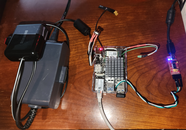
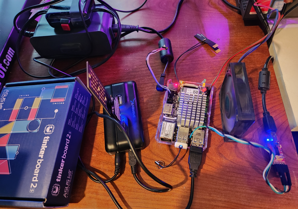
- Added by author - case, and power supply, fan optional.
- (optional) Keyboard, mouse, HDMI cable, and FTDIboard-with-miniUSB cable
Peripherals
| Component | Make/model | Status | Kernel driver(s) | Notes |
|---|---|---|---|---|
| PMIC | Rockchip RK808 | Works | rk808 | Power Management Integrated Circuit (Regulators, Clocking)[3][4] |
| Ethernet PHY | RTL8211E | Works | realtek_phy | via RGMII |
| Analog Audio | Not Present |
Board Layout
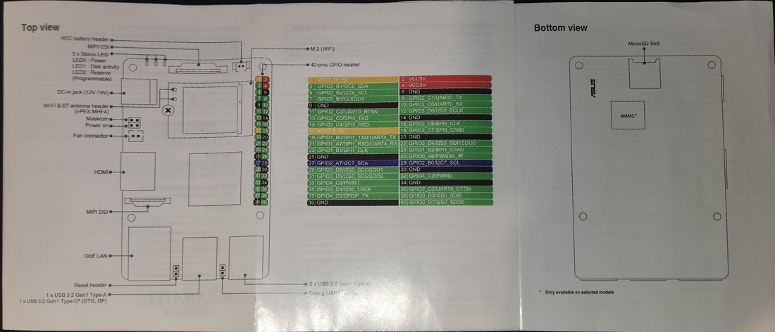
Mask ROM, eMMC Recovery jumpers
The TinkerBoard and TinkerBoard 2 S come with a four-pin header for setting jumper(s) to enable recovery of the contents of the eMMC. When set to "Mask ROM" and connected via USB to a PC, the board's boot process will bypass the bootloader on the eMMC and the board will appear as a USB-attached flash storage device. This enables the user to easily (re)flash write an OS image to the eMMC.
Jumper configurations
board  "default disable"        "eMMC Recovery"
edge       aka "Park"           aka "Mask ROM"
  |     jumper position         jumper position
  |
  |         +      +                +      +
  |                                        |
  |                                        |
  |         +------+                +      +
Alternatively, with the jumper in this position while a bootable SD card is inserted in the SD card reader, then the board will boot from the SD card. Thus, the author has replaced the normal jumper with a SPDT switch, to enable easy selection of one of two bootable storage devices.
Boot device select switch
               "eMMC
board         Recovery"
edge       (boot SD card)
  |              |
  |              |
  |       +      +
  |            \
  |             \
  |       +      + ---- COM
  |       |
  |       |
  |    default
  |    disable
  |  (boot eMMC)
There is also a "Power ON" jumper setting that documentation indicates can be used when the DC power supply is not switchable, to power down the board. The author has not tested this.
board      "Power On"
edge       (untested)
  |     jumper position
  |
  |         +      +
  |         |
  |         |
  |         +      +
Serial Console Setup
To use for troubleshooting and viewing bootloader console output, connect Debug UART RX/TX to a serial/USB converter as described in the TinkerBoard Developer Guide.
The TinkerBoard 2 defconfig sets up the bootloader to use UART2 (stty2) on Debug UART header pins. Also note Armbian u-boot default baud rate is 15000000
GCC optimization[5]
/etc/portage/make.confRK3399 exampleCOMMON_FLAGS="-mcpu=cortex-a72.cortex-a53+crc+crypto -mfix-cortex-a53-835769 -mfix-cortex-a53-843419 -O2 -pipe"
CFLAGS="${COMMON_FLAGS}"
CXXFLAGS="${COMMON_FLAGS}"
For a hardened system consider appending
-fstack-protector-allGentoo Installation Options and Procedures
Getting to Know the Board
The purpose of this guide is to document "from scratch" procedures for installing a pure gentoo system on this SBC. However the quicker way to get Gentoo up and running is to install another distribution, and replace the root file system contents. Start by consulting User:Brendlefly62/Rockchip_RK3399_Asus_Tinker_Board_2_S/Getting to Know the Board
Bootloader Build and Installation
To build a U-Boot bootloader from sources, see Build-Install-U-Boot
Assemble a Working Gentoo System
To assemble a working Gentoo system with minimal effort, using resources developed above, consult Assemble a Gentoo System
Kernel Build and Installation
To build a gentoo linux kernel (including modules, device tree blobs, etc) from sources, see build_install_kernel
Install a Gentoo System "From Scratch"
By Hand
To "manually" build a linux system from scratch, see linkname_tbd
With some automation...
To build a gentoo linux system with tools that automate many of the steps entailed in procedures described above, see linkname_tbd
Binary Kernel/Firmware packages
To use pre-built binary packages for linux kernel, molules, dtbs, and bootloader, see linkname_tbd/Pre-built-binary-packages
Bootable gentoo system images
To use pre-built bootable system images files, see linkname_tbd/Bootable-System-Images
Issue 1
When X happens, Y is how you fix it.
See also
(Optional section.)
External resources
- https://www.asus.com/us/networking-iot-servers/aiot-industrial-solutions/all-series/tinker-board/
- https://github.com/TinkerBoard/TinkerBoard/wiki/Developer-Guidecaution: tinkerboard vs tinkerboard2
- https://github.com/TinkerBoard/TinkerBoard/wiki/Developer-Guide#how-to-use-serial-console-debug
- How to Compile Armbian: Step-by-Step Tutorial for Beginners , first visit circa 23 September 2023
- Debug output in "somewhat successful build" First accessed 28 September 2023 (useful lsmod list and dmesg hardware/driver recognition information)
- https://opensource.rock-chips.com/wiki_U-Boot#Build_U-Boot
- https://github.com/u-boot/u-boot/blob/master/doc/README.rockchip
- https://u-boot.readthedocs.io/en/latest/build/source.html
- Old Gentoo Forums discussion of Gentoo on TinkerBoard
- Debian Kernel releases for TinkerBoard
- https://github.com/TinkerBoard/TinkerBoard/wiki/Developer-Guide Old Tinkerboard developer guide
- https://github.com/TinkerBoard/TinkerBoard/wiki/Developer-Guide#how-to-use-serial-console-debug
- https://github.com/TinkerBoard2 TinkerBoard 2 repository
References (Footnotes in the text above)
- ↑ PINE64 ROCKPro64#Issues
- ↑ https://gitlab.manjaro.org/manjaro-arm/packages/core/uboot-rockpro64/-/issues/4
- ↑ https://www.mail-archive.com/debian-bugs-dist@lists.debian.org/msg1903318.html
- ↑ Fuzhou Rockchip Electronics Co., Ltd., RK808 Datasheet V0.8 (PDF), PINE64. Retrieved on January 25th, 2021
- ↑ PINE64 ROCKPro64#GCC optimization

